Indian construction industry is growing rapidly, despite of low percentage of growth due to covid impact the industry is likely to register growth of 10.7% in FY22. Indian government has come up with huge investment in Infra sector with sole purpose of uplifting the construction sector growth. However the unproductive issue is the major challenge in the sector which leads to time & cost overruns, this is where the BUILDING INFORMATION MODELLING comes in picture. BIM has the capability to Visualize & Plan the project right from initial phase to final phase.
BIM DIMENSIONS
- BIM 3D - BIM 3D refers to "Information Modelling or Information Model" were 2D drawings are converted into 3D models with inclusion of 3 geographical dimensions (x, y, z). This enables the user to visualize the project in all there parameters.
- BIM 4D - The fourth Dimension of BIM is "Time" were the schedule details are added to the 3D model (LOD 300) to create Planned Vs Actual Simulations, Various forms of Look ahead's in terms of Project progress, Material requirements & Labour requirements.
- BIM 5D - The fifth Dimension of BIM is "Cost" were the cost details are added to 3D model. It helps to predict budgets at initial stages as well as helps to track project in terms of cost till the completion stages.
BIM WORKFLOW (3D, 4D & 5D)
 |
| BIM WORKFLOW |
BIM Workflow is divided in two parts 1. Pre-Construction Phase & 2. Construction Phase, explained in detail in following Steps
Part 1 - Pre-Construction Phase
Step 1: 2D CAD Drawings Requirement
Initially we require all sets of detailed designs or Good for Construction 2D CAD drawings of all disciplines (Architecture, Structure & MEP). Once these drawings are avaliable it is very important to store them in proper data management systems like BIM 360 Docs which helps to track the revisions of particular drawing.
Step 2: Schedule Development
As per the project scope the schedule model is prepared were activity sequence is created and relationships of project progress are assigned to them with duration i.e. Planned Dates, further the Actual dates are updated as per the project progress. The main objective of creating a project schedule is to analyze the activity sequences, resources requirement, duration of project & schedule constraints. Once the approved schedule from client side is avaliable Naming standards for Model development are prepared that helps in smooth linking of 3D model with Time aspect.
Example of Naming Standards of Substructure works
WBS L1 - Tower Name
WBS L2 - Structure Works
WBS L3 - Sub Structure
WBS L4 - Basement 3 (Floor Names or Level Names)
WBS L5 - Element Names (Columns, Beams, Staircases, Ramps, Slabs, Footings etc.)
Step 3: Model Development
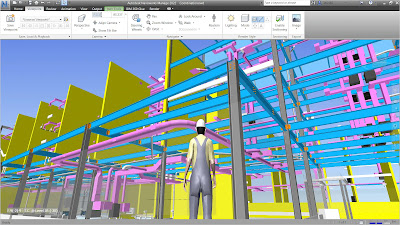
Once the drawings are avaliable models are developed discipline wise by the respective modelers. The Request for Information i.e. RFI are created and send to respective discipline consultants in case of any discrepancies in drawings. Also it is very important to provide model with the assigned naming standards as per the project schedule. Clash detection process is conducted once all 3 disciplines models are avaliable. Clashes encountered in the process are resolved and a Clash Free coordinated model is created.
Modelling Software's - Revit, ArchiCAD, Civil 3D, Buildertrend, BIM Object etc.
Clash Detection Software's - Navisworks, Bexel Manager, Solibri etc.
Step 4: Attaching Time Aspect to 3D Model
After the development of Constructible Model we are in position to link project schedule with 3D Model. As we have given the naming standards in 3D model as per project schedule it becomes very easy to link the dates in software's like Autodesk Assemble, Bexel Manager etc. In the attached image below we can see on the right side all model properties are arranged where as on left side imported project schedule can be seen. Linking both of them with planned and actual dates helps to get various reports as mentioned below -
- Planned Vs Actual Simulations.
- Monthly Look Ahead Plans.
- Monthly Labour & Material Requirements (when Labour Constants are avaliable from site team).
- Monitoring of Milestones.
- Critical Path Monitoring.
Software's - Bexel Manager, Assemble, Synchro etc.
 |
Link Rules tab from Bexel Manager
Source - Bexel Manager Website
|
Step 5 - Attaching Cost Aspect to 3D Model
Cost attachment is bit difficult task than attaching time aspect to the model. If the cost is attached in the schedule itself it becomes very easy to link the cost items with model & schedule elements. But when we get the cost through Budget it is a lengthy process. We need to create a cost classification as per the schedule activities. Also the cost needs to be adjusted of the non model elements like Anti Termite Treatment to milestones costs. Once the cost are classified as per schedule elements we follow the same procedure to link cost with model elements. Linking both of them with planned & Actual costs helps to get various reports as mentioned below -
- Monitoring of Schedule invoice.
- Monitoring of Planned cost with Actual cost.
- Preparation of Job Cost report.
- Monitoring of Schedule Direct & Indirect Cost.
- Monitoring of Sale Projections.
Software's - Bexel Manager, Assemble, Synchro etc.


%5D%2026_05_2022%205_53_08%20PM.png)


